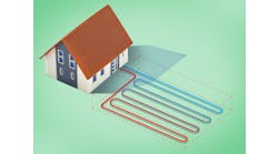
MARTHA’S VINEYARD, MA — This geothermal rescue was for a closed loop geothermal system that was seriously overheating during the cooling season. This system had ten vertical loops that served 11 heat pumps in three houses. Loop temps climbed and climbed during the summer until the heat pumps tripped on high pressure faults—the loop had hit 110° F. Our task was to increase the cooling capacity and restore cooling to the three houses connected to this system.
As an experiment, we flushed out the hot geo water with cold well water at 50° F and we were able to get another week of operation before loop temps hit 110° F again. Clearly, the ground temps were very high and could not absorb any more heat from the geothermal system.
Changing Times
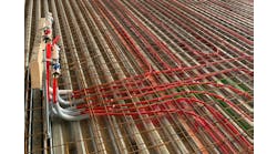
A geothermal system’s long-term success is dependent on a balance between heat extraction and heat rejection. The three houses used boilers to heat their radiant floors in the winter, so heat was never extracted from the geothermal field during the winter. This increased the possibility of heat saturation of the geothermal field over the years of operation.
Additionally, the original geothermal system was designed for a cooling setpoint of 76° F. This meant that the size of the geothermal field was fairly modest. This was not unusual on the Vineyard for that era when there was an expectation that homeowners would appreciate the ocean breeze for cooling.
However, the younger generation that now used the houses wanted much lower cooling setpoints… we regularly saw occupants setting thermostat setpoints between 65° F and 72° F. Cooling the houses to 72° F or 70° F was a struggle for both the outside geothermal field and the aging R22 geothermal heat pumps.
During the previous summer, we had seen the heat pumps go off on high pressure faults because the geothermal water temperature was too high at 105° F. Clearly, average ground temps were rising, and we were going in the wrong direction.
Plan of Action
There were two directions to take to resolve this situation (besides telling the kids to leave the thermostats set to 76°!)—add more closed loop geothermal wells or install a fluid cooler. Both directions would be effective in dropping the temperature of the geothermal loop water, but a fluid cooler turned out to be less invasive, easier to site, and ultimately less expensive.
We chose a dry cooler because there would be less annual maintenance. We sized it at 25 tons so that it could handle the entire cooling load of all three houses in the event that the vertical geothermal loops were to develop a leak.
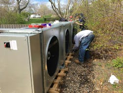
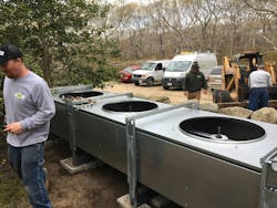
The fluid cooler we selected had three cooling fans with variable speed drives that could modulate based on loop water temperature. Because of the coastal environment, we specified solid copper fins (might as well have been solid gold—this added another $20,000 to the cost of the unit).
Installation
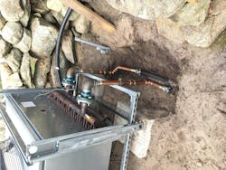
Our next task was to integrate this fluid cooler with the existing geothermal system. We were able to locate the unit behind the Carriage House (regular folks call that a garage). We were able to connect the fluid cooler via closely spaced tees to the main geothermal loop that connected the Main House and the Carriage House.
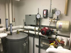
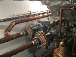
Inside the Main House, we had to rework the geothermal piping near the loop circulators to accommodate the added flow necessary for the remotely located fluid cooler. The loop circulators would send flow to both the main house heat pumps and the fluid cooler balanced with Victaulic balancing valves.
Though it was a tight footprint we were able to mount both balancing valves for easy access and service; the balancing valve on the left was for the main house heat pumps and the balancing valve on the right was for the new fluid cooler. (55 gpm and 40 gpm respectively). We also installed a booster circulator on the fluid cooler loop to assist with the 40 gpm flow.
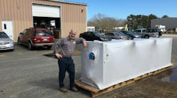
Once we received the fluid cooler, we opened it up for inspection—no damage to the fins was found. This fluid cooler weighed 1,300 pounds dry.
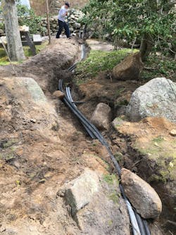
We installed 1-1/2″ HDPE well pipe supply and return lines from the back of the Carriage House to the remote location of the fluid cooler. We ran copper lines through the side wall of the mech room and transitioned to the well pipe below grade.
The fluid cooler was about 80 feet from the back of the Carriage House, so we had to size the fluid cooler circulator pump for the friction loss of the pipe and the fluid cooler.
Final Steps
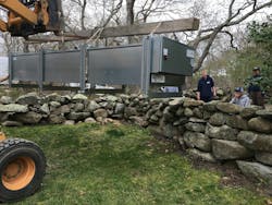
To prepare the fluid cooler for the move to its final location, we removed the adjustable legs and three fans, motors, and fan guards. We then used a Bobcat to carefully lower the fluid cooler into its upright position.
To provide the necessary rigidity during the transport to its final location, we placed a 16-foot-long timber across the top of the fluid cooler and assembled ratchet straps to the timber.
We carefully lifted the fluid cooler and adjusted the ratchet straps to ensure that the unit was not sagging or bowing. The fluid cooler itself was almost all copper inside and any tweaking of the alignment of the body would result in a permanent deflection. This we very much wanted to avoid as it would lead to broken braze joints and fan clearance issues.
Our Bobcat operator carefully crept forward with the fluid cooler trying to minimize swinging and jerking of the fluid cooler / timber assembly.
While the fluid cooler was being rigged and slowly transported, the NMD team was carefully leveling the concrete blocks that the fluid cooler would sit on. A lot of measurements were made to ensure that the installation of the fluid cooler could be done in one move.
The move slowed as the Bobcat, fluid cooler, and timber approached the ancient stone wall. We weren’t allowed to move any stones—they had been placed there back in the 1700s!
The critical part of the move was approaching as we started to lift the fluid cooler above the stone wall. We made extensive measurements of the reach of the Bobcat’s forks at different elevations to make sure we would clear the stone wall and have room to reattach and adjust the support legs.
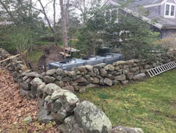
The fluid cooler cleared the wall, and we lined it up with the landing pad and reattached the legs.
Once the legs were bolted at the correct height, we lowered the fluid cooler onto the concrete blocks and we unstrapped the long wooden timber.
We carefully measured the fluid cooler and determined that there was no deflection in the body and the top and sides were level and plumb—no damage to braze joints or seams.
Enough room was left between the wall and the cooler to permit planting of shrubs and trees to further hide the unit from the driveway.
We assembled a framework of strut to support the supply and return connections at the fluid cooler, then we made the final connections to the 1-1/2″ plastic poly supply and return pipes that came from the Carriage House. We completed the re-piping of the Carriage House mechanical room to accommodate the supply and return pipes from the fluid cooler and connect to the outside geothermal loop.
We adjusted the three cooling fans in a thermal cascade—each fan would turn on if the water was 2 degrees hotter than its setpoint. We found that the system was able to run using only two fans for most of the summer due to our generous sizing of the fluid cooler.
We tested operation and landed at a geothermal loop temp of 90° F with all eleven heat pumps in the three houses at a cooling setpoint of 65° F. No more cooling complaints!
Brian Nelson is a Master Plumber and co-owner of Nelson Mechanical Design. Since 2004, NMD has been a “green” mechanical contractor specializing in energy- and water-efficient systems and serving the heating and cooling needs of the residents of Martha’s Vineyard.
