
Nelson Mechanical Design was asked to investigate an underperforming chilled water system at a large home overlooking the south coast of Martha’s Vineyard. The installing contractor had been let go due to their inability to get their system to work successfully and we were asked to perform a chilled water rescue.
The house was unbearably damp and humid in the summer—the cooling system was reaching the cooling setpoint in all six zones, but little to no dehumidification was occurring. We noted right away that the discharge air temperature was around 61 °F at the four air handlers but the chilled water temperature at the chillers was 44 °F. Something was seriously compromising the delivery of 44 °F chilled water to the air handlers. No wonder the house was uncomfortable!
Existing Equipment
The house had four air handlers split up into six zones and three 5 ton Daikin Altherma air to water heat pumps/chillers located in a chiller pit 300 feet away from the house. Each of the four air handlers had a chilled water coil piped to a three-way zone valve and a hot water coil connected to a hot water loop served by two wall hung Buderus boilers. We determined that one of the Altherma heat pumps/chillers had developed a leak over the winter that ended up shorting out everything inside. To complicate the problem, we weren’t able to find parts for it anymore.

There were no plans or any documentation of the system, but it appeared that the cooling load could be met by two of the three heat pumps. We gathered that at some point the Daikin Altherma heat pumps had provided first stage of heating and that that had been abandoned after the first winter.
Do We Need to Rip This Open?
Our next step was to dig into the existing installation to understand the original design and to figure out where things went astray. As often happens with these rescue projects, the homeowner had become so frustrated with their chronic cooling issues and complete lack of dehumidification in their vacation home that they allowed us to dissect their HVAC installation.
We started digging and found lots of issues and lots of design confusion. The heat pumps in the remote chiller pit (300 feet away at the end of the rolling lawn) were satisfied on loop temp, but the house was sweaty and miserable. Clearly the heat pumps were not being connected to the dehumidification load.
Chiller Pit Piping Issues
The three heat pumps in the chiller pit had their own internal circulators and were connected to a reverse return chiller loop. The 300 foot supply and return pipes from the main house were connected via closely spaced tees to this chiller loop.

This made sense as each chiller would see chiller loop temp and cycle on and off to maintain their setpoint. Unfortunately, no thermometers had been installed so the original contractor didn’t realize that the return water from the main house was mixing with the chilled loop supply water and compromising cooling capacity for the entire house.
Because the closely spaced tees were backwards, we measured 42° F in the chiller loop and 48° F for the supply water going up to the house. Yikes! That was an easy fix with press fittings; we added thermometers so we could see our chilled water temperatures.
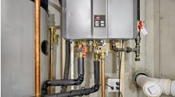
Mech Room Design Confusion
Insulating a chilled water system is a tough job and it was a shame to have to strip all of this nice insulation off to make our piping changes. We immediately noted that the system as it was installed was mixing return water from the air handlers with chilled water supply coming up from the chiller pit. As in the chiller pit, this piping confusion compromised the cooling ability for the entire house.

The existing Grundfos Magna circulator connected the remote chiller pit 300 feet away with this mechanical room—our pressure drop calculations told us that it was large enough to provide the necessary flow between the chiller pit with the three 5-ton chillers and the chilled water system of the house.
Each of the four air handlers had its own chilled water circulator. Due to inadequate pipe size between this mech room and the four air handlers each of these circulators would need to be replaced with a larger unit.
Finally, the two existing buffer tanks were starting to rot out so they would need to be replaced.
And Even More Design Confusion!

At each of the four air handlers, we stripped back the pipe insulation to reveal more design confusion. Each of the four air handlers had its own chilled water circulator in the mech AND its own three-way zone valve at the coil. Why use both? We thought that perhaps the air handlers were installed first and the thought may have been that the Magna circulator would be large enough to do ALL of the pumping. When they figured that it wouldn’t be able to handle all of the flow they added a circulator to each air handler zone.

We discovered that all of the chilled water coils were piped in backwards as well! Entering water was going into the coil nearest the return air and leaving water was leaving the coil on the air supply side, which meant that leaving water temps were in the low 60s, and discharge air temps were in the low 60s. We also noted that there were no thermometers and no air separators. What a recipe for inadequate flow and air bound systems!
Mech Room Corrections

Once we had finished our investigation, the re-design and re-pipe was fun and easy. We installed a new buffer tank and disconnected the mixing of chilled water supply coming from the chiller pit with air handler return water. We connected the Magna circulator to the buffer tank and the chiller pit 300 feet away and installed larger circulators for each air handler zone. Finally, we connected the supply for the four new circulators to the buffer tank so each zone would get 44 F water. We insulated our work using Armaflex instead of fiberglass insulation.
Air Handler Corrections
At each of the four air handlers, we chopped out the three-way Taco zone valves and piped supply and return lines directly to the chilled water coil. Each air handler also got an air separator and thermometers before and after the chilled water coil. We finished with Armaflex insulation.
Chiller Pit Replacement
The last part of our work was to replace the failed Daikin Altherma with a new 5 ton Aermec heat pump/chiller. We disconnected the Daikin from the chiller loop and yanked it out with an excavator and gently dropped in the new Aermec. Unfortunately, Daikin and Aermec don’t talk to each other so we had to install an HBX staging control to handle staging on and off the three units.
Success!

The homeowner arrived and the system was put to the test. Chilled water at each air handler was now 44 °F like it should be. Discharge air temperature was now at 52 °F which was well below the dewpoint. Relative humidity in the house dropped and dropped from 75% down to 40%.
Even though it was humid and hot outside, the homeowner was cool and dry inside. We noted that all three chillers were running during start-up as we had finally connected them successfully to the cooling load of the house. The homeowner was happy—another successful chilled water rescue!