Quite some time ago, I wrote an article addressing all of the different kinds and types of alternative energies. The articles were primarily based on the types and availability of these alternative energies, and didn't really get into the nuts and bolts of how to interface these precious Btu generators into existing heating systems. With the recent resurgence of alternative energy coming back around, I thought it would be a good idea to cover these nuts and bolts in words and drawings to make sure that our efforts to conserve energy are not lost to the wind.
For the record, if you have not noticed this before, I am a big fan of high (modulating/condensing) and ultra high (heat pumps) efficiency heat generating equipment for my comfort systems. With that said, I can't make the assumption that every system that alternative energy systems are applied to will necessarily fall within those two categories. In reality, their (high and ultra high efficiency) standby losses are so minimal that it would be hard to screw up the installation and possibly lose any Btus through the auxiliary heating system.
Such is not true of older, atmospheric natural gas-fired appliances. In most cases, the cast iron, copper and steel heat exchanger surfaces of these dinosaur-like appliances act as excellent radiators of precious Btus. Some older models do not even have a flue damper to slow the flow of heat pouring from the appliance in an off or standby position. In certain cases, with a highly elevated vent stack termination, compounded stack losses of older heating equipment can quickly and efficiently waste the precious Btus being introduced by the alternative energy systems — this is not a wise or efficient thing to do with precious energy derived from expensive equipment.
In most cases, it will be necessary to completely change the methodology of original piping used in order to avoid these unnecessary compounded energy losses. However, in every case, it will be beneficial to the end user in the form of increased overall system efficiency.
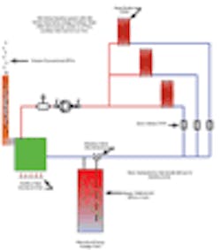
We'll begin with a drawing of a typical heating system and the improper way to interface. For reasons of simplicity, the drawing depicts a conventional, home run multizoned hot water heating system. These systems typically have three or more zones of hot water heat with a parallel direct-return manifold system on the near boiler piping. Over the years, system installers have taken to the habit of interfacing the piping between the alternative energy source and the auxiliary heat source on the return piping. The thought was that this was the point of lowest temperature, therefore, the best place to interface the lower temperature system. Although this sounds like a great theory, the problem is that the very first item that the low grade Btus will see is the appliance's heat exchanger, which is usually somewhat conductive and is probably cool to begin with. This results in a good amount of Btus being lost to the unnecessary heating of the appliance's heat exchanger, which does absolutely nothing to raise the temperature of the building to which it is attached. If the appliance is older, the losses from the stack effect of the appliance's chimney could be sending those precious Btus straight up the flue pipe and into the wild blue yonder, compounding the loss of heat, therefore, wasting even more precious energy.
Even in situations where the low grade alternative energy is interfaced down stream of the auxiliary heat source, the residual heat will eventually make its way back to the auxiliary heat source, and it will still waste energy! All of this is due to the fact that the conventional heating system and the alternative energy system are essentially in series with each other. The key to all of this is the use of primary-secondary piping and to follow some basic piping rules of thumb, hence, the near boiler piping configuration requirement will be completely changed to reflect this principle.
One of the first rules is that the piping between the two interface tees should be done as closely as possible. I prefer the use of a ball valve between the two closely spaced tees to aid in the purging of the heating system and distribution system. If you choose to follow this method, you must use a full port ball valve to avoid the potential of creating a pressure differential between the two tees, causing unwanted flow, which could possibly result in wasted energy. One of the most commonly overlooked principles of primary-secondary piping that is violated has to do with the amount of straight pipe before and after the secondary take off tees on the primary run. This may result in unwanted flow and wasted energy. There should be no induced flow into the secondaries if the installer always provides at least five pipe diameters of straight pipe before and after the secondary tee connections.
Tune in next month as we continue our search into the perfect hydronic interface between the old and new alternative energy technologies. Until then — Happy Alternative Energy Hydronicing.
Mark Eatherton is a Denver-based hydronics contractor. He can be reached via e-mail at [email protected] or by phone at 303/778-7772.
About the Author
Mark Eatherton
Mark Eatherton material on this website is protected by Copyright 2017. Any reuse of this material (print or electronic) must first have the expressed written permission of Mark Eatherton and CONTRACTOR Magazine.
