Nelson Mechanical Designs, Installs Huge Solar Radiant System
MARTHA’S VINEYARD, MA — Nelson Mechanical Design installed a 20-collector solar hot water drain back system to provide pool heat, radiant floor heating, and domestic hot water pre-heat for a customer. It features a 700-gallon storage tank, main and booster circulators, and motorized mixing valves to optimize the use of collected solar energy. It is the largest solar hot water system on Martha’s Vineyard.
Solar Collectors Recessed in Roof
The architect wanted an array of two rows of ten collectors each and wanted them to sit flush with the garage roof surface. This created some interesting design challenges. Usually, two or three solar collectors are mounted together on a roof and their mounting is fairly simple—each collector is clamped onto a strut assembly attached to the roof.
Because the solar collectors were recessed into the roof line to make them flush with the roof, the piping and strut assembly would be inaccessible once the collectors were in place and the entire assembly had to fit within the recessed area.
Thermal Expansion Challenge
We calculated that the width of the ten collectors would grow and shrink by 1″ over the course of the day from thermal expansion and we had to accommodate for that movement.
This meant that our solar collectors AND the piping would have a considerable amount of movement from the expected expansion and contraction. To simplify our installation, we chose to split the rows of ten collectors into rows of five collectors with central supply pipes running vertically in the middle. We had two supply pipes handling the upper left and lower left rows of five collectors and two supply pipes handling the upper right and lower right rows of five collectors. By doing this, we had reduced our thermal expansion to ½” for each row of five collectors.
The return pipes were routed on the outside edges of the collector array—the two left return pipes connected to the left upper and lower banks of five collectors and the two right return pipes connected to the right upper and lower banks of five collectors.
Sliding Collectors
We installed a series of horizontal rows of strut onto the roof surface. We then clamped the upper and lower central collectors firmly to the strut. The other four collectors of each group were connected to the strut by special clips that would permit sideways movement. This meant, for example, that the upper left row of five collectors would have the rightmost collector clamped to the strut and the other four collectors of that group could slide horizontally left and right as thermal expansion dictated.
This meant that the supply pipes in the middle could be clamped to the strut and the return pipes on the outer edges of the collectors would move ½” as they heated up and cooled down.
Custom Solar Roof Boots
After the first few collectors were in place, we could move forward with confidence that our approach worked. Once all the panels were in place, we had to make the piping connections to the end collectors. Roof boots were custom assembled out of copper to permit expansion of copper pipes carrying hot solar water without letting in the elements from outside.
Drain Back Pitch Considerations
The twenty collectors fit nicely in their recess in the roof line. Because the inside of the garage ceiling was finished, we had to “negotiate” with the architect to ensure that we would have adequate room for our solar piping. Because it was a drain back system, it was critical that the pipe size and pitch were sufficient to permit easy draining of the water out of the collectors—this occurred if the solar storage was hot enough, if there was no Sun, and if it was nighttime.
Solar Storage
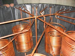
In the mechanical room in the basement, we installed the 700-gallon storage tank and the copper coils that were dedicated for pool heat, radiant heat, and domestic hot water pre-heat.
Because of the low system pressure of the solar system, we were able to use a large rubber liner and insulated aluminum wall to assemble the storage tank. This simplified the installation and reduced system cost compared to installing multiple smaller storage tanks. This 700-gallon storage tank had a large insulated cover to reduce heat loss into the basement mechanical room.
Copper Coil Heat Exchangers
Once the copper coil heat exchangers were installed in the storage tank, we were able to connect them to their loads—two of the copper coils were connected to the domestic hot water system and assisted in pre-heating domestic hot water. Two of the copper coils were connected to the radiant floor heating system on the return side; they were able to heat up the radiant system water returning to the boiler which effectively reduced fuel consumption by the boiler. The last two copper coils were connected to a titanium plate and frame heat exchanger that was connected to the pool heater return line. As with the radiant connection, the solar hot water would heat the pool water going back to the pool heater, thereby reducing fuel consumption by the pool heater.
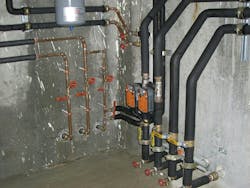
Motorized Valves
We installed motorized valves on the radiant, domestic hot water, and pool heat connections to permit flow through the copper coil heat exchangers when heat was needed, and heat was available from the solar storage tank.
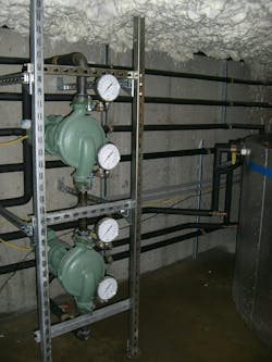
Solar System Pumps
A main and booster circulator pump setup was installed—when the control system called for flow to the solar collectors, both of the pumps would run to lift the water up to the top of the solar collectors. Once a siphon was established, we only needed to maintain enough pressure in the system to prevent the siphon from failing. We could do this with just one pump so the other pump was de-energized.
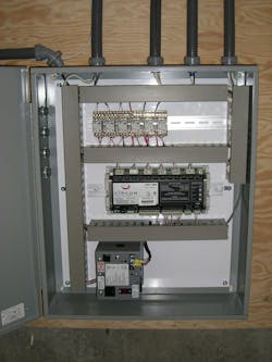
Direct Digital Control System
We assembled a DDC system to integrate all solar system functions. We were able to measure the temperature of the upper left, upper right, lower left, and lower right rows of five collectors. We also measured the temperatures of solar supply and return pipes, radiant supply and return, pool supply and return, DHW supply and return, and the solar storage temperature.
The DDC system was able to compare solar collector temps versus solar storage temps to determine if the main and booster pumps should start operation. The motorized valves let us optimize the use of the solar storage by constantly looking at pool, DHW, and radiant return temps to see when the solar storage tank could contribute to offset fossil fuel usage.
System Operation and Maintenance
The added complexity of the drain back system—ensuring adequate pipe size and slope to ensure drainage of all of the collectors and the main and booster pumping strategy—permitted using water instead of a glycol mix in this solar system. This resulted in reduced annual maintenance costs beyond the minimal cost of treatment of the water to protect the cast iron circulators.
System Success
This solar installation has eliminated the need for fossil fuels to heat the pool and significantly reduced the fuel used by the boiler for radiant and DHW production.
Parts and Suppliers
Solar Hot Water collectors by AET (Alternative Energy Technologies)
Circulator pumps by Taco
Motorized ball valves by Belimo
Controls by Circon
Solar Tank by SPP HydroFlex Atmospheric Solar Tanks
About the Author
Brian Nelson
Brian Nelson is the co-owner of Nelson Mechanical Design, a “green” mechanical contractor serving the energy efficiency and home comfort needs of Martha's Vineyard, MA since 2004. The company designs, installs, and services just about anything to do with heating, cooling, domestic hot water, water treatment, geothermal, heat pumps, and radiant. NMD is committed to preserving the fabric of the Island it calls home. To learn more visit nmdgreen.com.
